Yes, again.
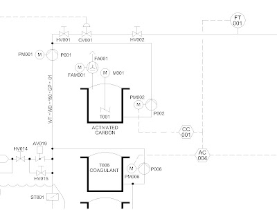
Just some added light. The above is a snip of one of my drawings using our new methods. We are in the process of trying to sort all our ones up to a reasonable standard, so I have had a talked with a man from Denmark I work with, and he has come up with some good ideas:
1. Tag numbers should have the form of AV007, or PM126, which would stand for Actuated Valve and Pump Motor respectively. The reason for the XX000 format is this allows for up to 100 items in the one area.
2. The temptation is to make PIDs based on an area, but it is better to make them on a process basis. This means a drawing could have a tank in one building with a pipe leading to another.
These processes would have an overall name, and number, which would be the drawing number.
So for instance you might have a drawing/file number like "PID-014-Carbonitation.dwg".
Therefore a tag in that drawing might be AV007, but it's true unique tag would be 014-AV007.
3. The idea is to keep the drawings as clutter free as possible, and to this end, arrows are not permitted, except if you are desperate! Also on the no-go list are temperatures, flow rates, motor kWs and other fluff. That fluff can go on the Flow Diagram or if need be a separate layout.
My ideas on the drafting are:
1. All text to be 1.5mm high. For mechanical drawings I use 2mm. Just need to squeeze that extra bit on!
2. All ordinary items (eg lines) to be on the med layer. I use the name med as short for medium line weight. I normally have this as set to yellow, but maybe if things needed to be printed in colour, then it might not be so clever. I have a colour ctb that prints yellow as black.
3. All viewports to be of scale 1:1.
4. All tag numbers to have their own layer, these layer sets are available in the template drawing and as a lisp routine to create the layer set. The reason for this is to be able to isolate the numbers so you can check them quickly to see if you have duplicated any.
5. Most of the symbols are to Iso standard 10628, in other words, a world standard.
6. The Tags to have their own block, which consists of the attribute only, no lines.
7. Instrument tags have their own circle and so on with two tags, as a dynamic block allowing the same block to be used in all 4 orientations. Handy when you want to extract data!
8. All items to be in model space. This allows for more than one layout, say for instance if you need one showing flow rates. The flow rates would end up in paper space.
I know people that use a grid to do PIDs, and I have tried this but found the whole process of turning snaps on and off all the time irritating.
My web page bilrocad.com was due to die about February 2012, but Blue Host, the provider, stayed the execution for another year, so I am going to try and make it a little more easy on the eye, as it looks very rough at the moment.
All this between getting another blog going for a Flying Boat (see the new link on the right)-
I have had a struggle getting the book reading bit going, but it is up and running now-see "A Noble Chance" on Friends of the Solent Flying Boat.
4 comments:
Thanks for sharing this useful info. Keep updating same way.
Regards,Siddu Corporate Training
Thanks for sharing this useful info. Keep updating same way.
Regards,Siddu Corporate Training
This is just the kind of information that I had been looking for a long time. Thank you very much for posting this blog its very nice..........................For More Information about Oracle Fusion Financials Training in online.
Nice one, You have clearly explained this concept. I had come to know about your internet site. It is very useful for me to understand. Keep on sharing.
Oracle Fusion SCM Training in Hyderabad
Post a Comment