Just had a look on Youtube at a demo of Autodesk's Plant 3D which I guess is an add-on to Autocad. It looks easy to use and produces things like isometric drawings with bills of materials.
From the short demo, I came away quite impressed. You can see one of the videos here: http://www.youtube.com/watch?v=gokkAr0Lc2I
It makes my home grown approach to piping look a little crude and backward. If you want a look at how I do this, go to: http://www.youtube.com/watch?v=nZsVUjbRWO4
Having said this, I could imagine how hard it would be to persuade decision makers at my work that this would be a good way to go, probably because my work about 20% piping. Well, I can dream can't I?
Even if I were certain that this was the way to go, there would be a nagging doubt that maybe other products such as Revit MEP might be the clever way.....
So, back to Youtube and what do you know? Here is a demo of Revit MEP,
http://www.youtube.com/watch?v=6Sf_b_Wes2s
To me, it looked like a lot of button pressing for not much result. So here is a puzzle: Autodesk make and sell both products.....why?
I don't want to be seen as a Revit basher here, because as I understand it, a lot of quite clued up people think that Revit is the way to go for drawings of buildings, so maybe I'm missing something.
Sunday, August 14, 2011


Friday, April 22, 2011
Acad.pat
A co-worker who uses Autocad LT to do his electrical drawings recently said he could not open one of my drawings, because I had saved it as R2010. I had recently been upgraded from Autocad R2008 to R2010, so I said:
"I believe you may be able to upgrade to the R2010 version".
Which he did, which in hindsight was not the best plan, as after installing he wanted to use the hatch command, and got a dialog saying:
"Cannot find acadlt.pat"
Which is fine: All you have to do is go Options, File Locations, and add where it is to your support path. Unfortunately, on the network, we are mere users and are not allowed access to our c: drive.
The IT man was duly called, and progress is on going...involving reimaging and so on.
Which made me think, why can you not get a copy off the internet, download it, stick it somewhere where you are allowed to go and add that location to your support listing?
Strangely enough, I was not able to find a copy of acad.pat anywhere!
Of course there were heaps of people giving out add-ons to the file, but not the file itself.
So here I am, Saturday morning of the 23rd of April, rummaging around my hard drive for the mysterious file. (Mad? Yes!). You can open it up in Notepad and check it out.
Here is part of it:
;;
;; Copyright (C) 1991-2011 by Autodesk, Inc. All Rights Reserved.
;; Version 2.0
;; AutoCAD Hatch Patterns
;;
;;
;; Note: in order to ease migration of this file when upgrading
;; to a future version of AutoCAD, it is recommended that you add
;; your customizations to the User Defined Hatch Patterns section at the
;; end of this file.
;;
;; Note: Dummy pattern description used for 'Solid fill'.
*SOLID, Solid fill
45, 0,0, 0,.125
*ANGLE, Angle steel
0, 0,0, 0,.275, .2,-.075
90, 0,0, 0,.275, .2,-.075
*ANSI31, ANSI Iron, Brick, Stone masonry
45, 0,0, 0,.125
It does go on for quite a bit more, as I have Autocad Architecture, then towards then end it has this bit:
;; User Defined Hatch Patterns
;; Add any hatch patterns that you define to this section of
;; the file to ensure that they migrate properly when
;; upgrading to a future AutoCAD version. If duplicate hatch
;; patterns are found in this file, items in the User Defined
;; Hatch Patterns section take precedence over patterns that
;; appear earlier in the file.
;;
I find it puzzling as to why the file is called acadlt.pat for LT, but maybe they are given less hatches out of the box.
STOP PRESS! According to Robin, a good plan is to run Autocad first time WITH ADMINISTRATOR RIGHTS! Should I tell the IT man?......
"I believe you may be able to upgrade to the R2010 version".
Which he did, which in hindsight was not the best plan, as after installing he wanted to use the hatch command, and got a dialog saying:
"Cannot find acadlt.pat"
Which is fine: All you have to do is go Options, File Locations, and add where it is to your support path. Unfortunately, on the network, we are mere users and are not allowed access to our c: drive.
The IT man was duly called, and progress is on going...involving reimaging and so on.
Which made me think, why can you not get a copy off the internet, download it, stick it somewhere where you are allowed to go and add that location to your support listing?
Strangely enough, I was not able to find a copy of acad.pat anywhere!
Of course there were heaps of people giving out add-ons to the file, but not the file itself.
So here I am, Saturday morning of the 23rd of April, rummaging around my hard drive for the mysterious file. (Mad? Yes!). You can open it up in Notepad and check it out.
Here is part of it:
;;
;; Copyright (C) 1991-2011 by Autodesk, Inc. All Rights Reserved.
;; Version 2.0
;; AutoCAD Hatch Patterns
;;
;;
;; Note: in order to ease migration of this file when upgrading
;; to a future version of AutoCAD, it is recommended that you add
;; your customizations to the User Defined Hatch Patterns section at the
;; end of this file.
;;
;; Note: Dummy pattern description used for 'Solid fill'.
*SOLID, Solid fill
45, 0,0, 0,.125
*ANGLE, Angle steel
0, 0,0, 0,.275, .2,-.075
90, 0,0, 0,.275, .2,-.075
*ANSI31, ANSI Iron, Brick, Stone masonry
45, 0,0, 0,.125
It does go on for quite a bit more, as I have Autocad Architecture, then towards then end it has this bit:
;; User Defined Hatch Patterns
;; Add any hatch patterns that you define to this section of
;; the file to ensure that they migrate properly when
;; upgrading to a future AutoCAD version. If duplicate hatch
;; patterns are found in this file, items in the User Defined
;; Hatch Patterns section take precedence over patterns that
;; appear earlier in the file.
;;
I find it puzzling as to why the file is called acadlt.pat for LT, but maybe they are given less hatches out of the box.
STOP PRESS! According to Robin, a good plan is to run Autocad first time WITH ADMINISTRATOR RIGHTS! Should I tell the IT man?......
Saturday, April 2, 2011
Autocad 2012 - 3dconfig


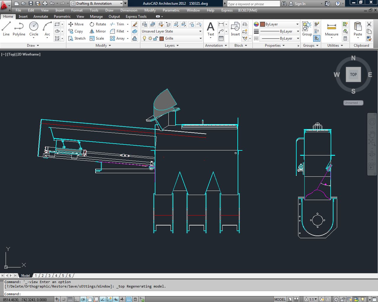
Well, here we go again, with another release of Autocad.
A quick verdict:
1. It seems nice to use, quick and responsive.
2. No new killer features, except that the section command seems to be doing what it should have done in R2007. Namely the colour of the cut lines seems to be OK now.
To me that is almost worth the upgrade.
3. The nicest thing I like is the display. I have an old quadro fx1500 video card and after updating the video driver, I used 3dconfig to enable hardware acceleration. At first I had rotten results, but after setting it to only have Gooch hardware shader, I found it performed a lot better.
The point is here that you need to update your video driver with a new version, and set it's usage to be not too overtaxing.
4. It has a lot of other stuff that I probably would not use, but I have to concede that my usage is not everyones! Things like 3d parametric arrays and so on.
5. Rendering seems a lot better.
6. As usual, a small upgrade, but all these small things add up over the years to make things a little easier. For instance hatching.
7. A little easy to miss is a new system for views-there is a new bit of text in the top left corner to select views, and visual styles. This comes under the heading of old dogs and new tricks.....woof.
It seems there is more and more stuff with each release. It shows up in the file size of the download (I don't bother with discs any more). It was a 1.4GB download.
Back in 2002, it seemed to fit on a cd.
I had a bit of fun installing: It seemed Nortons noticed a good time to do a background scan, which froze things up a bit. Never mind, do a "restore point". That failed as well, and I was just considering dealing to the whole hard drive, when I tried again and it seemed OK. This time, I hovered around and pounced on Nortons as soon as it came up and killed it off.
The picture of the house I did in Autocad Architecture 2011 as a concept for a friend, which shows what gooch shading looks like.
If you want a quick roundup of all the features, nicely presented, go see:
http://www.ellenfinkelstein.com/acadblog/autocad-2012-new-features/
Thursday, January 6, 2011
Last Post for a While


A New Year's Resolution...haul back on the blogging and do something more useful.
Probably something to do with not a lot of feedback.
This post is about a porch roof I designed. My wife requested a cover over our front door so you don't have to get wet when it rains...it rains lots in Auckland. My original idea was a repeat of the roof nearby,ie tiles, rafters etc.
Then I saw one a friend had done: Just a sheet of glass held up by steel brackets.
Just to be competitive I designed a similar one, but this one used stainless steel. Originally, I chose 40 x 5 flat bars as the material, but the look was not all that "architectural", so I redesigned it to use a profile cut shape as the support part.
Wednesday, December 29, 2010
Why getting into Architectural Drafting might not be a good idea....

You may not agree with this, but give Autodesk's new Homestyler a try out.
I have tried out previous attempts by Autodesk to do this sort of thing, but this is way out in front as far as usability and so on.
It's primary function seems to be for interior layouts and it is is very good at these. Outdoor layouts are catered for as well, but it appears a pretty flat world out there.
I could see my friends computer-phobic wife getting onto this and producing a kitchen or two.
In the pic, I just slammed in some furniture and hit the render button, and it produced a fairly good render.
There are some things it does not seem to do:
1. Allow you to make your own content.
2. The window content is a little sparse as yet, but might grow.
What this shows is the shape of things to come: The tools of designers will become so effortless to use, that anyone can produce drawings. The new job of architect might then become what it should be: a dreamer, artist etc.
I'm still waiting for something similar to come along for mechanical drafting.....
http://usa.autodesk.com/adsk/servlet/pc/index?siteID=123112&id=14943677
http://usa.autodesk.com/adsk/servlet/pc/index?siteID=123112&id=14943677
Saturday, December 18, 2010
Yet another Golden Rule broken....again
What Golden Rule? The one that says:
"If you draw everything, then there is less surprises in store for you!"
Recently, I had to draw a simple platform next to a dust extractor. The purpose of the platform was to enable maintenance persons to get access to Stuvex bottles. These bottles are an anti-explosion device and as far as I know, sense and explosion and release some sort of dampening gas so the explosion is nullified.
Just to make life complicated, it was located up alongside an old wall, which had pipes, electrical trunking and so on either side of a corrugated iron wall. I have found out the hard way, that it is easy for a draftsman to say- "This pipe will be in the way....it will have to be moved." "Yeah, but, where to?!" Easier drawn than done it appears.
The platform ended up being on 2 levels, and the lower one looked fine in the plan view: Yes, fine until you asked yourself: How to get it in that place? Fortunately, the man on the job is highly intelligent and made it bolted so it would fit in. Except there was a brace, not drawn, apparently in the way. Not a big deal, it can be relocated, but to have noted this on the drawing would have saved drafting embarrasment.
Which highlights a problem found often in drafting: You need to bash together a concept drawing, and then go through numerous changes to the design before it solidifies. By the time that happens, you are quite convinced that your drawing is accurate and wonderful.
At this point the thing to do is kick your own butt out onto the site and site check your critical dimensions. I do this now by forcing myself to put these dimensions on the drawings and putting heavy boxes around critical dimensions.
I guess the lesson I'm slowly learning here is that the initial site measuring should be thorough and accurate and not to trust old drawings, even ones that were done by yourself.
Finally, a quote sent to me that seems on the nail:
"We moderns have managed to combine an incredible mastery of technical knowledge and information with an astonishing ignorance of the traditional wisdom once possessed by an illiterate village elder, and evident for all to see on every page of history.
Spend more than you earn and you’ll go broke.
Give someone something for nothing, and he’ll soon expect something for nothing on a regular basis.
Fail to hold people accountable for their bad behavior, and they’ll continue to act badly.
Give people an excuse to fail, and they’re more likely to fail.
Let aggression go unpunished, and you’ll get more aggression."
-Bruce S. Thornton
The guy who sent me this one made the following suggestion:
(except substitute 'we moderns' with 'dimwitted lefties')
"If you draw everything, then there is less surprises in store for you!"
Recently, I had to draw a simple platform next to a dust extractor. The purpose of the platform was to enable maintenance persons to get access to Stuvex bottles. These bottles are an anti-explosion device and as far as I know, sense and explosion and release some sort of dampening gas so the explosion is nullified.
Just to make life complicated, it was located up alongside an old wall, which had pipes, electrical trunking and so on either side of a corrugated iron wall. I have found out the hard way, that it is easy for a draftsman to say- "This pipe will be in the way....it will have to be moved." "Yeah, but, where to?!" Easier drawn than done it appears.
The platform ended up being on 2 levels, and the lower one looked fine in the plan view: Yes, fine until you asked yourself: How to get it in that place? Fortunately, the man on the job is highly intelligent and made it bolted so it would fit in. Except there was a brace, not drawn, apparently in the way. Not a big deal, it can be relocated, but to have noted this on the drawing would have saved drafting embarrasment.
Which highlights a problem found often in drafting: You need to bash together a concept drawing, and then go through numerous changes to the design before it solidifies. By the time that happens, you are quite convinced that your drawing is accurate and wonderful.
At this point the thing to do is kick your own butt out onto the site and site check your critical dimensions. I do this now by forcing myself to put these dimensions on the drawings and putting heavy boxes around critical dimensions.
I guess the lesson I'm slowly learning here is that the initial site measuring should be thorough and accurate and not to trust old drawings, even ones that were done by yourself.
Finally, a quote sent to me that seems on the nail:
"We moderns have managed to combine an incredible mastery of technical knowledge and information with an astonishing ignorance of the traditional wisdom once possessed by an illiterate village elder, and evident for all to see on every page of history.
Spend more than you earn and you’ll go broke.
Give someone something for nothing, and he’ll soon expect something for nothing on a regular basis.
Fail to hold people accountable for their bad behavior, and they’ll continue to act badly.
Give people an excuse to fail, and they’re more likely to fail.
Let aggression go unpunished, and you’ll get more aggression."
-Bruce S. Thornton
The guy who sent me this one made the following suggestion:
(except substitute 'we moderns' with 'dimwitted lefties')
Saturday, November 27, 2010
He hates Autocad....not really...Part 2 of Excel to Autocad


 I showed my PLC Excel application (see my previous post) at work , and the man said, yes, it had promise. As usual, someone else said "The address numbers are not right!" Ok.
 So here I have wasted another sunny day (actually, if I go into the sun here in NZ for more than 15 minutes, I get burnt) fiddling with this stuff.
I have done a few changes, mainly the buttons that were embedded in the spreadsheet have now been transferred to a User Form, this is activated by the Quick Access menu. It just allows the user to scroll up and down and get the buttons to show only when necessary.
The range of equipment is now light, relay and solenoid valve. The silly idea of having each line drawn has been ditched in favour of block that just gets inserted.
The existing drawings like to tell the viewer that this is an "alarm light". Which seems extra work when you have a symbol that conveys that information. Same for the solenoid valve.
I did toy briefly with the idea of downloading the IEC 6017 electrical symbols. Yes, you can, but they cost. I had some doubts as to the snapping I should be using, but I figure if this all goes ahead and someone says they want 2mm snaps instead of 1.5mm, then it would not be that horrible to change.
Subscribe to:
Posts (Atom)