About one year ago at work I started work on a project to install a new packing machine where I work.
In my usual carefree fashion, I organised one drawing to do this. Even though I had my newly developed lisp routine to turn on the stuff on the ground floor and freeze the levels above, it proved cumbersome, especially as I was unable at the time to use my favourite: SECTIONPLANE. At one stage, I even created a new empty drawing and xreffed the main drawing into it and used 3DCLIP to get a clearer idea of what was going on.
In the beginning, it was "only" a proposal, so all this was not really that critical. All that mattered was "Would it fit, and in what configuration." Now this is a full on project, things are a lot more critical: you have to know where everything is, and what all clearances are to ensure no surprises on judgement day.
I noticed the engineer in charge did not seem all that happy with the drawings, in that it was hard to visualise some parts due to the fact that some things hide other things, so I have decided to rethink my strategy.
We are now going to have a drawing for each machine, and they will be xreffed into a main drawing which will be mostly just a floor with a reference point in it. Walls and doors will be on one drawing, steelwork on another.
The machine drawings will be in 3D and have all their views, dimensions and annotations in paper space.
Now I am able to use the sectionplane command, there will be one drawing that shows sections, by xreffing in the main drawing to it.
Wednesday, July 25, 2012
Saturday, June 23, 2012
Everybody draws Process and Instrumentation Drawings...don't they?
This just goes on and on. Just when I thought I was nearing half way, the "man" said to me:
"Bill, of course you are doing a Bill of Material for every drawing?"
After picking myself up off the floor after a fainting attack, I replied:
"This will take me centuries!"
Fortunately, I had sort of prior knowledge of this (I appear to filter out unwanted information),
so I had devised a block named "TAG" for valves, motors and so on, and one called "INSTRUMENT" as explained in my March 6th 2012 blog.
Writing a lisp to collect all the tag ones and list them in a text file was pretty easy and went well. You might be asking why did I not use Eattext, a newish command to do exactly this? It is OK, but involves lots of button pressing dialog box travelling.
No, I wanted a one button approach. Silly me. Turns out my dynamic block is a nasty little beast. Do it as per the tag system and it makes a mess of the count.
Searching the net showed me that there are really clever lisp programmers out there, but none had written exactly what I needed.
One came close, a man called Doug Broad, who put up a bare bones solution, using Visual Lisp.
It turns out that Visual Lisp extends ordinary lisp, and allows you to solve such a problem as this.
To use visual lisp in a lisp routine, just type: (vl-load-com). After much frustration, this routine seems to work:
 This is a scrap from a typcial P & ID, the instruments are the ones in bubbles.You can see there are quite a few non-essential lines, and maybe it is not done in slick elegant manner, but it it is relatively easy to follow.
Here is the routine:
;Program written by Bill Le Couteur
;Auckland NZ
;Rev 0 date 24 June 2012
;This program EXTRACTS ALL THE BLOCKS CALLED TAG AND INSTRUMENT
;AND CREATES A TEXT FILE WITH THE ATTRIBUTES
(defun c:PIDE()
;;;this file is the LISTING file
;;;;this makes sure file is empty
(setq scrfile ( open "C:/Bilro/Bilro4/LISTING.TXT" "w"))
(close scrfile)
(setq scrfile ( open "C:/Bilro/Bilro4/LISTING.TXT" "w"))
(setq count 0)
(setq SS1 (ssget "X" (list '(0 . "INSERT") (cons 2 "TAG"))))
(setq no_of_entities ( sslength ss1))
(while (/= count no_of_entities)
(progn
(setq en (ssname ss1 count))
(setq ed (entget en))
(setq the_attrib (entget (entnext en)))
(setq the_tag (dxf 1 the_attrib))
(print the_tag)
(write-line the_tag scrfile)
(setq count (+ count 1))
);end progn
);end while
;;;;;;;;;;;;;;;;;;;;;;;;;NOW TO FIND THE DYMNAMIC BLOCKS CALLED "INSTRUMENT";;;;;;;;;;;;;;;;;;;;;;;;;;;;;;
(vl-load-com)
(setq ss2 (ssget "_X" '((0 . "INSERT"))));;;ESSENTIAL-FIND ALL THE BLOCKS FIRST!!!!!!
(setq no_of_entities (sslength ss2))
(setq count 0)
(setq innercount 0)
(print no_of_entities)
(while (< count no_of_entities)
(progn
(setq obj (vlax-ename->vla-object (ssname ss2 count)))
(setq itsrealname (vla-get-Name obj))
(setq itseffectivename (vla-get-EffectiveName obj))
;(print obj)
;(print itsrealname)
;(print itseffectivename)
;(if (eq itseffectivename "INSTRUMENT")(PRINT "HELLO THERE"))
(setq en (ssname ss2 count))
(setq ed (entget en))
;(print ed)
;;;;;;;;;;INNER WHILE LOOP::::::::::::::::::::::::::-only if its name is "INSTRUMENT"!
(if (eq itseffectivename "INSTRUMENT")
(progn
(while (< innercount 2)
(progn
(setq en (entnext en))
(setq ed (entget en))
(if (eq innercount 0)
(progn
(setq atag (dxf 1 ed))
;(print atag)
);end little if progn
);end little if
(if (eq innercount 1)
(progn
(setq the_no (dxf 1 ed))
;(print the_no)
(setq instrument_tag (strcat atag the_no))
(write-line instrument_tag scrfile)
;(print instrument_tag)
);end little if progn
);end little if
;(print count)
;(print innercount)
;(print ed)
(setq innercount (+ innercount 1))
);end while progn
);end while /= sequend
);END IF PROGN
);END IF
;;;;;;;;;;INNER WHILE LOOP::::::::::::::::::::::::::
(setq innercount 0)
(setq count (+ count 1))
);end while progn
);end while
(close scrfile)
(princ)
)
(defun dxf(code elist)
(cdr (assoc code elist)) ;Finds the association pair, strips 1st element
);defun
"Bill, of course you are doing a Bill of Material for every drawing?"
After picking myself up off the floor after a fainting attack, I replied:
"This will take me centuries!"
Fortunately, I had sort of prior knowledge of this (I appear to filter out unwanted information),
so I had devised a block named "TAG" for valves, motors and so on, and one called "INSTRUMENT" as explained in my March 6th 2012 blog.
Writing a lisp to collect all the tag ones and list them in a text file was pretty easy and went well. You might be asking why did I not use Eattext, a newish command to do exactly this? It is OK, but involves lots of button pressing dialog box travelling.
No, I wanted a one button approach. Silly me. Turns out my dynamic block is a nasty little beast. Do it as per the tag system and it makes a mess of the count.
Searching the net showed me that there are really clever lisp programmers out there, but none had written exactly what I needed.
One came close, a man called Doug Broad, who put up a bare bones solution, using Visual Lisp.
It turns out that Visual Lisp extends ordinary lisp, and allows you to solve such a problem as this.
To use visual lisp in a lisp routine, just type: (vl-load-com). After much frustration, this routine seems to work:

Here is the routine:
;Program written by Bill Le Couteur
;Auckland NZ
;Rev 0 date 24 June 2012
;This program EXTRACTS ALL THE BLOCKS CALLED TAG AND INSTRUMENT
;AND CREATES A TEXT FILE WITH THE ATTRIBUTES
(defun c:PIDE()
;;;this file is the LISTING file
;;;;this makes sure file is empty
(setq scrfile ( open "C:/Bilro/Bilro4/LISTING.TXT" "w"))
(close scrfile)
(setq scrfile ( open "C:/Bilro/Bilro4/LISTING.TXT" "w"))
(setq count 0)
(setq SS1 (ssget "X" (list '(0 . "INSERT") (cons 2 "TAG"))))
(setq no_of_entities ( sslength ss1))
(while (/= count no_of_entities)
(progn
(setq en (ssname ss1 count))
(setq ed (entget en))
(setq the_attrib (entget (entnext en)))
(setq the_tag (dxf 1 the_attrib))
(print the_tag)
(write-line the_tag scrfile)
(setq count (+ count 1))
);end progn
);end while
;;;;;;;;;;;;;;;;;;;;;;;;;NOW TO FIND THE DYMNAMIC BLOCKS CALLED "INSTRUMENT";;;;;;;;;;;;;;;;;;;;;;;;;;;;;;
(vl-load-com)
(setq ss2 (ssget "_X" '((0 . "INSERT"))));;;ESSENTIAL-FIND ALL THE BLOCKS FIRST!!!!!!
(setq no_of_entities (sslength ss2))
(setq count 0)
(setq innercount 0)
(print no_of_entities)
(while (< count no_of_entities)
(progn
(setq obj (vlax-ename->vla-object (ssname ss2 count)))
(setq itsrealname (vla-get-Name obj))
(setq itseffectivename (vla-get-EffectiveName obj))
;(print obj)
;(print itsrealname)
;(print itseffectivename)
;(if (eq itseffectivename "INSTRUMENT")(PRINT "HELLO THERE"))
(setq en (ssname ss2 count))
(setq ed (entget en))
;(print ed)
;;;;;;;;;;INNER WHILE LOOP::::::::::::::::::::::::::-only if its name is "INSTRUMENT"!
(if (eq itseffectivename "INSTRUMENT")
(progn
(while (< innercount 2)
(progn
(setq en (entnext en))
(setq ed (entget en))
(if (eq innercount 0)
(progn
(setq atag (dxf 1 ed))
;(print atag)
);end little if progn
);end little if
(if (eq innercount 1)
(progn
(setq the_no (dxf 1 ed))
;(print the_no)
(setq instrument_tag (strcat atag the_no))
(write-line instrument_tag scrfile)
;(print instrument_tag)
);end little if progn
);end little if
;(print count)
;(print innercount)
;(print ed)
(setq innercount (+ innercount 1))
);end while progn
);end while /= sequend
);END IF PROGN
);END IF
;;;;;;;;;;INNER WHILE LOOP::::::::::::::::::::::::::
(setq innercount 0)
(setq count (+ count 1))
);end while progn
);end while
(close scrfile)
(princ)
)
(defun dxf(code elist)
(cdr (assoc code elist)) ;Finds the association pair, strips 1st element
);defun
Saturday, April 14, 2012
Process and Instrumentation Diagrams (PIDs)...but wait ...there's more!

Hmfff.....looks like I was wrong thinking 1.5mm high text was a good idea.
It so happened that one of our electrical engineers has just had an eye operation and was having an awful time trying to read my drawings.
I realised they would have to be changed to 2mm high, which a huge nuisance as I have done quite a few drawings.
Just to add to the fun, it appears that the requirement is for each sheet to show mainly just one item, so a drawing might only have one tank, with it's associated piping and pumps. So the emphasis is still on systems, just at a finer level.
The drawings I had done were not wasted, as they became the detailed PROCESS FLOW DIAGRAMS. Some upside to this as I have a bad habit of trying to squeeze too much onto one drawing usually.
I have started on a lisp routine to deal to errant drawings: it is called FIX.lsp. When it is up and running I will post it.
In the meantime, in a rush of enthusiasm that has just evaporated, I have just gotten the skeleton of a routine together that should make PID drudgery a little easier.
The idea of the routine, called ADTAGS.lsp, is that you have done all the graphical elements of your drawing, that is you have drawn all the valves and pipelines in, and you now wish to add tags to all the items in the drawing. For instance you may have 3 manual valves, and you want to label them with tags, HV001,HV002 and HV003, as per the picture above.
Here is the routine, which is obviously far from finished:
;Program written by Bill Le Couteur
;Auckland NZ
;Rev 0 date 14-4-12
;This program adds tag numbers to a bunch of blocks
;only works for blocks named "VALVE MANUAL" at the moment
(defun c:ADTAGS()
(setq count 0)
(setvar "attdia" 0); turns off the dialog box you get when issuing ate commmand
(setq ss1 (ssget "X" '(( 0 . "INSERT")( 2 . "VALVE-MANUAL")) ))
;gets a selection set of the whole drawing, filtering for the block we want
(setq the_no_of_members(sslength ss1))
;how many members in the selection set?
;;;;;LOOP THROUGH THE SELECTION, GETTING POSITION INFO AND USING THIS TO
;;;;;SET THE INSERTION POINTS;;;;;;;;;;;;;;;;;;;;;;;;;;;;;;;
(while (< count the_no_of_members)
(progn
(setq en (ssname ss1 count))
(setq edata (entget en))
(setq theposn(cdr(assoc 10 edata)))
(setq the_x (car theposn))
(setq the_x ( - the_x 5))
(setq the_y (cadr theposn))
(setq rot (cdr (assoc 50 edata)))
(if (eq rot 0)(setq the_tagy (+ the_y 4)))
(if (/= rot 0)(setq the_tagy (- the_y 1.5)))
(if (/= rot 0)(setq the_x ( + the_x 9)))
(setq counts (itoa count))
(if (eq rot 0)(setq the_tag (strcat "HV00" counts)))
(if (/= rot 0)(setq the_tag (strcat "HV00" counts)))
(command "-insert" "tag" (list the_x the_tagy) "1" "1" "0" the_tag)
(setq count ( + count 1));add one to the counter to keep the loop going
);end while progn
);end while
(setvar "attdia" 1);turns on the dialog box you get when issuing ate commmand
(princ)
)
Friday, March 30, 2012
Rough Visualising of ideas
We have a man at our work who has an infectious enthusiasm for new ways of creating electricity.
Much fun has been had proposing all sorts of wild schemes involving kites and so on. I have a digital camera that can take movies, so I decided to experiment with it to present one of my ideas. A patent search revealed some similar ideas, but not precisely this one. I'm not sure on the business with patents, but I think that seeing as this idea is now out in the wild, no one can patent it.
It would be nice if someone with a bit of money and enthusiasm picked it up and ran with it.
The idea is very simple. You have a series of windmills, held aloft by a balloon, but they are better than a similar size at ground level, because the winds are faster the higher you go.
Tuesday, March 6, 2012
Process and Instrumentation Diagrams (PIDs)

Yes, again.
Just some added light. The above is a snip of one of my drawings using our new methods. We are in the process of trying to sort all our ones up to a reasonable standard, so I have had a talked with a man from Denmark I work with, and he has come up with some good ideas:
1. Tag numbers should have the form of AV007, or PM126, which would stand for Actuated Valve and Pump Motor respectively. The reason for the XX000 format is this allows for up to 100 items in the one area.
2. The temptation is to make PIDs based on an area, but it is better to make them on a process basis. This means a drawing could have a tank in one building with a pipe leading to another.
These processes would have an overall name, and number, which would be the drawing number.
So for instance you might have a drawing/file number like "PID-014-Carbonitation.dwg".
Therefore a tag in that drawing might be AV007, but it's true unique tag would be 014-AV007.
3. The idea is to keep the drawings as clutter free as possible, and to this end, arrows are not permitted, except if you are desperate! Also on the no-go list are temperatures, flow rates, motor kWs and other fluff. That fluff can go on the Flow Diagram or if need be a separate layout.
My ideas on the drafting are:
1. All text to be 1.5mm high. For mechanical drawings I use 2mm. Just need to squeeze that extra bit on!
2. All ordinary items (eg lines) to be on the med layer. I use the name med as short for medium line weight. I normally have this as set to yellow, but maybe if things needed to be printed in colour, then it might not be so clever. I have a colour ctb that prints yellow as black.
3. All viewports to be of scale 1:1.
4. All tag numbers to have their own layer, these layer sets are available in the template drawing and as a lisp routine to create the layer set. The reason for this is to be able to isolate the numbers so you can check them quickly to see if you have duplicated any.
5. Most of the symbols are to Iso standard 10628, in other words, a world standard.
6. The Tags to have their own block, which consists of the attribute only, no lines.
7. Instrument tags have their own circle and so on with two tags, as a dynamic block allowing the same block to be used in all 4 orientations. Handy when you want to extract data!
8. All items to be in model space. This allows for more than one layout, say for instance if you need one showing flow rates. The flow rates would end up in paper space.
I know people that use a grid to do PIDs, and I have tried this but found the whole process of turning snaps on and off all the time irritating.
My web page bilrocad.com was due to die about February 2012, but Blue Host, the provider, stayed the execution for another year, so I am going to try and make it a little more easy on the eye, as it looks very rough at the moment.
All this between getting another blog going for a Flying Boat (see the new link on the right)-
I have had a struggle getting the book reading bit going, but it is up and running now-see "A Noble Chance" on Friends of the Solent Flying Boat.
Monday, January 2, 2012
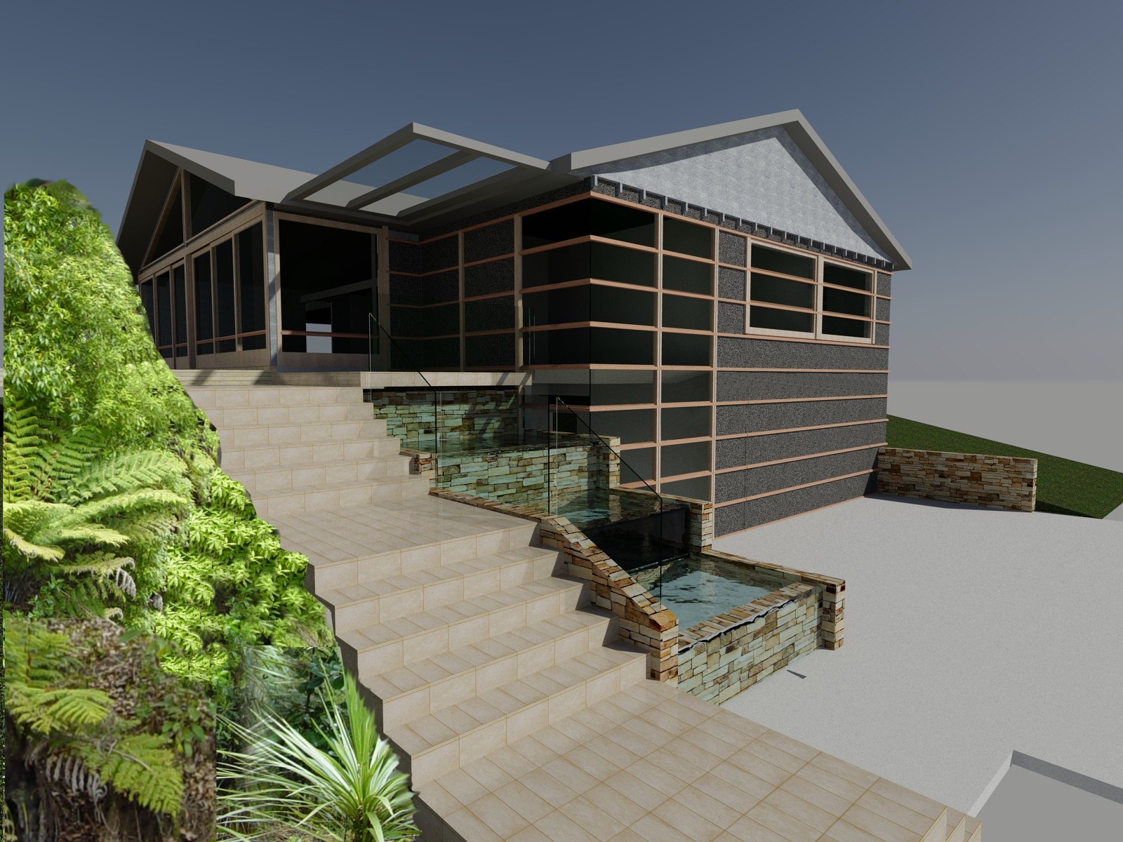
Just a few renders...
What you see here is the result of a bit of experimentation. With Autocad the trick is to make sure LIGHTINGUNITS is set to either 1 or 2 and that you have sky background and illumination selected. It also pays to open the Advanced Render settings and make sure Final Gather is ON. The foliage in the foreground was cut and pasted in afterwards in Photopaint.
No Sky needed in the night shot but it seems it stayed on anyway!
These are a friend's design, the first is a renovation of the front of an existing house and the second is a bachelor pad, to go in a large backyard. The first one has scorched weatherboards.
Apparently this protects the wood for about 80 years.


Subscribe to:
Posts (Atom)