Saturday, November 20, 2010

He hates Autocad down by the sea shore...

Hate is probably too strong a word. Prefers to avoid might be better. He is an electrical person who organises motors to start, stop and so on. He will never read this, but just in case I will refer to him as "Fred" (not his real name).

This is done by means of PLC's (Programmable Logic Controllers). My knowledge of these is limited to the following:
They have cabinets, and in these cabinets are "racks" and in the racks are "cards".

The cards are where the wires from say a relay are connected to. It appears Fred is quite OK with Excel and happily puts all his stuff into a spreadsheet. If the electricians were happy with this, instead of a drawing, then life would be easy.

But no. They like drawings, done in Autocad because that has been the way of things for quite a while. Recently, he gave me some drawings to update, which involve me typing hundreds of times the same thing over and over again. Words like REMOTE and FAULT. I have now requested we get a program called "Active Words" which just stores up your keystrokes and you can allocate hot keys to them.

This all triggered an idea (no doubt not new!) to see if I could give Autocad an Excel connection.
The plan was to have a spreadsheet all set up with buttons on it to make filling it out a quick thing, then a button to generate an Autocad script file. I did this once years ago, and have no idea where all the files ended up, so thought it might be fun to do a new approach. It is summer here now in Auckland and maybe fun might be getting out to the beach.

Another wasted weekend later, I have a bare bones setup that works. It was a struggle with Microsoft Excel 2007, as I was used to the 1997 version. Little differences like: you have to have a macro enabled file type, the ribbon where things seem to be never where you think they might be. Plus, if you want VBA, you have to add the "Developer" tab to the ribbon.

Here is a screen shot of the spreadsheet:

This is a snippet of the VBA screen, showing part of the code:


This one is a shot of a typical autocad drawing of a PLC card:


This one here shows a line of script generated lines and text:

They have only got LT Autocad, so a script is the only way here. I have been down this rocky road before in a way: I tried to do the same thing, but using their existing blocks, which became a nightmare.
This time: no blocks, just lines and text, it is just simpler. Having said that, the line shown was hard coded-ie the coordinates of everything had to be specified. If this goes any further, there would have to be a lot of number adding and string converting.
That's if....


Saturday, November 6, 2010

Menu Pulldowns


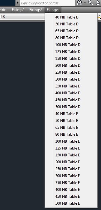
I have often wondered why Autocad does not ship with useful stuff as shown above. Even if it was supplied as a .mnu file, then it would be a 5 minute task to have it up and running should user want it, without cluttering up a standard installation.
The obvious answer is that Autodesk has to look after all it's 3rd party add-on sellers. Just a commercial reality I suppose.
The Flanges just come in as a block. The Fixings1 items come in as individual bits. Fixings2 - they come in as "combos" ie a set of head, flat washer, spring washer, and nut.
To make one of these for yourself is not that hard.
Just fire up Notepad (Look under Start/Programs/Accessories)
and type in something like this:

***MENUGROUP=BILRO1

***POP13
[Fixings1]

[M6 Bolt Head] -insert;"C:/cad/library/3D/fixings/bolter/m6headb";\1;1;0;

Then save it as not a text file, but with a ".mnu" on the end so the file name ends up something like Bilro1.mnu.
The syntax looks a bit arcane, but just go with the flow.... You can see where the path is, and the block name (ie just another dwg file) is, and all the ;\1;1;0; is a shorthand way of saying:
enter,pause,use a scale factor of 1 for X,enter, scale factor of 1 for Y,enter,use a rotation of zero,enter.
To sum up:
; means enter
\means pause for user input
Then you have the fun of getting it into Autocad, so just:
1. Right click on any toolbar, and choose customise.
2. See the little round button with the arrow down the bottom? Hit it.
(There is someone in Autodesk that loves to hide things....)
3. Now pick the Transfer tab up the top.
4. Hit the 2nd button from the right, one that should give a tooltip of "open customisation file".
5.When the dialog comes up look down the bottom-it will say something like "...cuix" or "cui", so change this to legacy files-mnu, and hunt for your file.
Although Autocad does not tell you this, I believe (I can always be wrong!) that it converts it to a cui or cuix file as you open it.
6. On the right panel, expand the + next to "Menus". You should see your new headings there.
7. On the left panel, do the same. You should see the standard menu headings there.
8. Go back to the right panel, pick your first item, hold down shift to select all your items, then drag and drop to the left panel in the position you would like them to occupy.
9. Hit OK.
After some humming and whirring, you should have your menu additions!
As you can see, the Fixings and Flanges are most likely foreign to you as here in NZ we use British Standard Flanges usually.
Now comes the part I had a lot of hassle with: What happens if you get the path name wrong, and need to update it? You would think it should be straight forward, but I did not find it that logical.
How to do it:
Do the same actions as above, but stop at item 7. On the left panel, right click on the items you have added previously and choose "delete". Yes, you are sure! Then from the right panel drag your headings back onto the left panel as before.
I am going to add a few more bits and pieces, and then I hope to post the whole lot as a bundle on http://bilrocad.com/

Sunday, October 24, 2010

Video Postings

I have been sort of busy doing some videos of my window frame drawing lisp set.

The above is an experiment to see if video embedding works.

The other videos can be found on youtube, just type bilrocad into the search box.

We had a long weekend here in Auckland, and I have been trying to find out how to stop huffing sounds when doing a video. (Maybe I should get a life? ...or paint the fence???)

For probably equally strange reasons I started doing a test of my Autocad skills on Brainbench, but made a bit of a hash of it and got a case of the "can't be bothereds" half way through. If you are tempted to do the test, make sure you have Autocad up and running before you start!

Friday, October 8, 2010

Sort of Autocad, and who is Nate Holt anyway?

Sometimes I end up doing electrical drawings, which is quite irritating, because I'm not sure what I'm doing. I did actually get a New Zealand Certificate, Electrical in 1988, which I never ever used. I did go for the odd job, only to be told (no doubt quite rightly!), how long were you a tradesman electrician? On hearing the answer, I was told to sling my hook.

So I know what a relay is etc, but how everything hangs together and why is a bit of a mystery to me.

Recently, I tried to look for a lisp that would allow me to align some text, and in the process of looking ended up at a blog page of a man called Nate Holt. My first reaction was: "Wow! This guy can really do a good job explaining things!" Check out his blog yourself at:

http://nateholt.wordpress.com/2010/08/24/add-sounds-to-your-too-quiet-autolisp-utility/

On digging a little deeper, it turns out he is someow connected to Autocad Electrical, that is a "vertical" of Autocad, meaning it tacks on or adds to standard Autocad. Which led me to:

http://download.autodesk.com/us/autocadelectrical/adm717_build_2006-07-21a/index.html

I had a look at some the videos, and have come away quite convinced that this would be the way to go if you had to do Autocad Electrical drawings.

Last week, one of my co-workers popped his head up and asked:

"Hey, how come I have updated the file on my desktop and the other one has also updated?"

I cannot claim the high ground here, because it was about 5 years ago that I discovered that Windows Explorer loves to duplicate the display of it's folders, only to be told "Everyone knows that!" Which apparently is not true, because this man did not know either.

Whoever made Windows Explorer decided to make it "easier to use" and in the process removed it's logicality. By the way, in case you did not know, you can access Windows Explorer by right clicking the Start button.

Here is the top level of the "Desktop" shown in Windows Vista, notice the folder called Pictures:


Double click on Pictures and you get a view of the folders in there:


Then, close everything up and you get:

Next, double click on Computer and then open up Users:


Now double click on Pictures....there are the same damn folders!


Which reminds me of the Microsoft Helicopter Joke:

A helicopter was flying around above Seattle yesterday when an
electrical malfunction disabled all of the aircraft's electronic
navigation and communication equipment. Due to the clouds and haze
the pilot could not determine his position or course to steer to the
airport. The pilot saw a tall building, flew toward it, circled, drew
a handwritten sign and held it in the helicopter's window. The sign
said "WHERE AM I ?" in large letters.

People in the tall building quickly responded to the aircraft, drew a
large sign and held it in a building window. Their sign said, "YOU
ARE IN A HELICOPTER." The pilot smiled, waved, looked at his map and
determine the course to steer to SEATAC (Seattle/Tacoma) airport and
landed safely.

After they were on the ground, the co-pilot asked the pilot how the
"YOU ARE IN A HELICOPTER" sign helped determine their position. The
pilot responded, "I knew that had to be the MICROSOFT building
because they gave me a technically correct but completely useless
answer."


Sunday, September 26, 2010

Blocks versus lines and things

I have been playing around with some joinery details, and it came to me that whoever drew them was thinking as he drew, with lines and so on. Once he had those lines, he saw no reason to alter them. Which is fine.

Only problem is, that he wanted to generate more sections based on them, things got a little messy, to the point where he must have said to himself:

"Funny? That dimension should have been 139mm....it is not actually that, on this model....oh well, let's just do a quickie here and alter the dimension text to read what I want instead of what it actually is".

Where's my big hammer?

The trouble is, when you are designing, it is wonderful to use lines etc, but once you have zeroed in on a particular size, make it into a block, so you don't inadvertently stretch it, plus you can reuse it, confident in knowing that it is a set piece of geometry.

I'm thinking here of a sectional view of a window sash.

Saturday, September 18, 2010

Video Productions and old 2D lisps

Once, long ago, last century I posted a heap of supposedly useful lisp routines on an old web site (now long gone). I have gone through these and reposted them on:

http://bilrocad.com/Lisps2d.html

I have also posted some ancient 3D ones on:

http://bilrocad.com/Lisps3d.html

It struck me that some of these are hard to use(!), so I have done a few videos, creating a special page for them at:

http://bilrocad.com/Videos.html

It was a bit of a learning curve doing them - they ended up with huge file sizes, so I downloaded a free converter and condensed them a bit.

Before 2000, I was interested in Virtual Reality Modelling Language (VRML) and sort of expected that this would evolve into something useful around about now. It appears not....although maybe I have not looked hard enough. I looked at all the old sites and most of them seem to be stuck around 7 years ago. Octaga seems to be the only one still chugging.

Saturday, September 4, 2010

Revisions...the last post...I promise! and Working with XREFS

Revision File Naming

About a year back I raved on about revision problems created by the fact that a drawing file might contain many layout tabs, where sheet 1 might be rev B and sheet 2 might be rev D.

My approach for the last year, which I now admit is one that has a major fault, was to remame the actual drawing file name so it reflected the fact that it was a later revision. For example 150283D.dwg. The "D" would represent the most advanced revision. Into a folder marked "History" went the old files, for record purposes.

This worked well until the man in charge of maintenance requested that we go back to the old format of 150283.dwg, because he had that number listed in his database package called Mainpac.

My new system, from here on, is to saveas the drawing into the History Folder as "150238 as at 12Aug2010", and keep the current one always as "150238.dwg". Always a brain strain to remember to saveas!

As well, the principle of Xreffing goes astray if you start changing file names. Xreffing is something I had avoided because people in the future would come unstuck if the masters of IT ever changed a name of a drive. (They would never do that....would they?)

If they replace me in the future, then part of that person's job is to understand the concept of xrefs and how to fix them if the drive is reanamed. With this in mind, I have started to use them sparingly.

A Different Way of working, using xrefs

We have a 3D models of the plant in a folder marked "Plant-3D Models". Each major building has a name, eg "Melthouse" and the file name is the same as the building name.

My idea is to gradually build these up so that they represent a true and more or less accurate model of what is currently there. In these models, there are section tools, which write out 2D sectional views to the appropriate folder.

Our setup is further complicated because we have 2 sets of drawings-One for proposals and one for things actually built. So if something went from a proposal to reality, I would have to change my xref paths. A further gotcha is my 3 step method:

  1. Model with section tool.
  2. Outputted section file.
  3. Presentation drawing with outputted section file xreffed in.
The benefit of this seemingly overly complex method is that the process of updating the Presentation file is quick and easy: Change the model, write out the section file, reopen the Presentation file and everything is updated more or less automatically.

I have mentioned this in previous posts, but not in the same format!

At the moment this system seems to work, but sometimes the model gets cumbersome. For instance I might be working on the basement area, and you tend to trip over all the other stuff just looking at that. I'm thinking of a lisp routine that freezes layers according to their names- for instance Level1-Plant might get hidden when I want only level2 stuff showing. Yes, this can be done with layer filters and the layer manager. The trouble with the layer manager is that it seems to choose to turn off layers and not freeze them. As well, if you create new layers, you have to update the layer definition in the layer manager.

There are other problems: The detail required of a large plant layout is usually better to be of a low level, whereas for say a tank, I usually make this quite detailed. How to mix and match the two? I don't have an answer as yet. Possibly the answer lies in a 64Bit machine with 12Gigs...?