Showing posts with label Lisp. Show all posts

Saturday, April 14, 2012

Process and Instrumentation Diagrams (PIDs)...but wait ...there's more!


Hmfff.....looks like I was wrong thinking 1.5mm high text was a good idea.

It so happened that one of our electrical engineers has just had an eye operation and was having an awful time trying to read my drawings.

I realised they would have to be changed to 2mm high, which a huge nuisance as I have done quite a few drawings.

Just to add to the fun, it appears that the requirement is for each sheet to show mainly just one item, so a drawing might only have one tank, with it's associated piping and pumps. So the emphasis is still on systems, just at a finer level.

The drawings I had done were not wasted, as they became the detailed PROCESS FLOW DIAGRAMS. Some upside to this as I have a bad habit of trying to squeeze too much onto one drawing usually.

I have started on a lisp routine to deal to errant drawings: it is called FIX.lsp. When it is up and running I will post it.

In the meantime, in a rush of enthusiasm that has just evaporated, I have just gotten the skeleton of a routine together that should make PID drudgery a little easier.

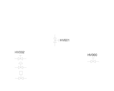
The idea of the routine, called ADTAGS.lsp, is that you have done all the graphical elements of your drawing, that is you have drawn all the valves and pipelines in, and you now wish to add tags to all the items in the drawing. For instance you may have 3 manual valves, and you want to label them with tags, HV001,HV002 and HV003, as per the picture above.

Here is the routine, which is obviously far from finished:

;Program written by Bill Le Couteur
;Auckland NZ
;Rev 0 date 14-4-12
;This program adds tag numbers to a bunch of blocks
;only works for blocks named "VALVE MANUAL" at the moment

(defun c:ADTAGS()
(setq count 0)
(setvar "attdia" 0); turns off the dialog box you get when issuing ate commmand

(setq ss1 (ssget "X" '(( 0 . "INSERT")( 2 . "VALVE-MANUAL")) ))
;gets a selection set of the whole drawing, filtering for the block we want

(setq the_no_of_members(sslength ss1))
;how many members in the selection set?

;;;;;LOOP THROUGH THE SELECTION, GETTING POSITION INFO AND USING THIS TO
;;;;;SET THE INSERTION POINTS;;;;;;;;;;;;;;;;;;;;;;;;;;;;;;;


(while (< count the_no_of_members)
(progn
(setq en (ssname ss1 count))
(setq edata (entget en))
(setq theposn(cdr(assoc 10 edata)))
(setq the_x (car theposn))
(setq the_x ( - the_x 5))
(setq the_y (cadr theposn))
(setq rot (cdr (assoc 50 edata)))
(if (eq rot 0)(setq the_tagy (+ the_y 4)))
(if (/= rot 0)(setq the_tagy (- the_y 1.5)))
(if (/= rot 0)(setq the_x ( + the_x 9)))
(setq counts (itoa count))
(if (eq rot 0)(setq the_tag (strcat "HV00" counts)))
(if (/= rot 0)(setq the_tag (strcat "HV00" counts)))
(command "-insert" "tag" (list the_x the_tagy) "1" "1" "0" the_tag)

(setq count ( + count 1));add one to the counter to keep the loop going

);end while progn
);end while

(setvar "attdia" 1);turns on the dialog box you get when issuing ate commmand

(princ)
)

Monday, January 4, 2010

On a video roll

I've gone mad with the uploading of videos to Youtube. The latest is for
handrails to be found at:

http://www.youtube.com/watch?v=XIJ4ZNz3rhk

I hope that I'm getting better at doing these- a friend suggested I work on a smaller
screen size and have the autocad background set to white, which seems to produce
a much better result.

Now, back to that Revit tutorial....

Friday, November 20, 2009

Now Anyone can draw handrails


Finally. The baby has arrived. hrail.lsp that is. A difficult birth, accompanied by much wailing and gnashing of teeth. Just as well that I was forced to take some days off work, otherwise it might never have been done. Last weekend it was "finished", that is until I tried it out on a real drawing: it crashed and burned when the pline had an elevation greater than 0.
I'm quite surprised that I managed to debug it today and get it ready to roll. It was a neat feeling to see it doing it's thing in the end.
Which makes me wonder why I should spend my limited time left on planet earth doing stuff that I end up giving away for free? Probably just mad. Seriously, I have wanted one of these for years now-and if nobody else wants it, big deal: I'm going to get a lot of fun out of using it.
It's a bit like someone doing crosswords-just a bit of a challenge and exercise for the brain, and if someone else gets some use, good.
It makes use of a dialog box, offering use of 6 different types (see the previous blog). The idea is to draw a pline CLOCKWISE around the floor edge of your steel platform, issue the hrail command, make your choices, and pick the pline to get the results shown above.
I'm making the files available only by email request to gauge if anyone is interested.
See http://bilrocad.com/Lisps3d.html for instructions on use.
I can be emailed on bill@bilroCad.com


Saturday, April 25, 2009

Everyone Draws Rectangular Flanges, don't they?


The other day I got sick of drawing yet another rectangular flange.
I thought: get smart-someone else must have done a lisp for this.
But no. At least as far as I looked- which was not all that far.
There was one found but it did not perform the way I wanted, so
I decided to write my own. Needless to say it appears to have
taken a day and half out of my life.


It occurs to me now, that my time would probably have been
spent better watching TV or taking Rose for a walk.


Anyway, it was a vague sort of challenge, and it is finished now.
One of it's features is that it does produce 3D solids when it
has finished. It also flies in the face of "traditional" methods
of spacing of bolts. Normally in the old days a draftee would
work out the bolt centres (theoretical) then choose the nearest
value to make the centres. For instance, he might have calculated
137.5mm as the hole centres. To make the drawing not have the
dreaded 0.5 or the "hard to read" 137, he would have said
nearest is 140mm. Then the dimension between the end hole
and the next one in might have ended up at say 122mm.


I have suddenly had an epiphany: all the flanges I have been
drawing lately have been laser cut. So who cares if the hole
centres are 137.5mm? Not me. Especially when it
made this routine a lot easier to write. No doubt the
traditionalists out there will be pouncing on me for being
so outrageous!


Here is the dialog box - where you fill in all the variables.


It does make the layers "Front Flange", "Back Flange"
and"Gasket", otherwise it does not appear to do anything
drastic to your drawing. I have made it so that it can be used
in an existing drawing-ie you don't have to run it in a new drawing.
I have had the odd situation (which I could not make it repeat)
where it seemed to lose the plot and put the holes in the
wrong place-almost as it the snapmode had gone nuts.
When I checked osmode, I got something like 16477,which is
a strange one, considering the whole thing just uses
standard commands and hopefully does not reuse Autocad's
reserved commands like angle and so on.
An extension I did consider was to insert bolts/nuts and washers.


Wednesday, December 24, 2008

Lisp: Everyone draws pipes don't they?


Of course they don't. I know that. Here is now made available, not exactly on a plate, a FREE, fun way to draw pipes. Not quite the end of drafting drudgery, but the start of the end!


Unfortunately, when I tried to put them on my blog all the lines ended up all over the place.

So I have made the decision to make the files available on a "request only" basis. That means you e-m-a-i-l me, asking for them, and I send them to you. (For free). I am trying to avoid the spammers here by saying think about blecouteur at xtra dot co dot nz.


In the process of testing: another snafu-the dialog box won't fit on the screen. This is because at work I have a big screen.....So I have now 2 dialog boxes to send you- one a chopped down one and one that is the full nine bananas. The small one does dairy pipes only-Grr...I will have to see about more columns...which can be done, it just makes life more complicated. It probably needs doing anyway. Try the full one called pipeset.dcl. if it does not work try the smaller one.


Every time I use this routine I am pleased at the appearance of pipes, as if by magic. There is a certain amount of ego stuff here, but I am at least honest enough to say that out there somewhere someone has done the same thing. (Probably a while ago.)

I had thought briefly of selling the combined routine, but they are very short routines, and any

capable lisp writer, if they had seen them being used, would be able to re-write them easily.


The idea is you run one routine initally to set the diameter of the pipe you want to be drawing.

The name of this routine is pipeset.lsp

Then you draw lines representing the pipe routes. Fiddle around with these to get them right.

Next, use pir.lsp to do the pipe radii. Unfortunately you have to do this elbow by elbow. One day I may make a routine to do this all in one hit.


Now comes the big moment: Set the routine pip.lsp onto that bunch of lines/arcs. That's right just select the damn lot all at once! Whoopee!....or it should be.


One of the routines uses a dialog box. This is contained in a separate file called a .dcl file.

The trick with this one is that the routine that accompanies it (pipeset.lsp), needs to know where you stuck it on your hard drive. You should be able to see the bit early on in the routine saying where the dialog file is kept.


Some people just get lazy and stick them all in the support directory, but this can be a pain if you upgrade.