Saturday, December 19, 2009
Maybe it's time for a break..
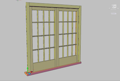
Anyway, this window stuff is now finished, and unless my friend R wants a set of horizontally sliding doors, or windows that slide up and down, this is now a project done.
That is, unless I get excited about doing a costing part.
The next project is to do a bit on Java. How this can be connected to Autocad I'm not sure and what the next project should be I'm not sure. Maybe it is just the time of year.
I had a flash of the blinding obvious regarding drawing of houses. It seems that almost every part of a house model is controlled by the floor plan. If you could have a program that generates a set of foundation plans automatically from a floor plan?
Same with the roof. Which just leaves the walls and windows. The exterior walls would be controlled by the floor perimeter, so they are covered. The exterior walls are then able to be enumerated and so windows as a separate item could be assigned to a particular wall.
That leaves just the interior walls. Maybe these are controlled by the "room usage"?
Which comes back to Java: I know this is an object oriented language and I have done a bit of research on it and it seems very good.
It now occurs to me that someone else has thought of all of the above, and is possibly feverishly putting the finishing touches on a program which, unfortunately, will put a lot of architects out of work.
Saturday, December 12, 2009
Just finished bashing my head against the keyboard
I have an all too convenient cold at the moment (this stops me from running/riding a bike/walking etc)-so I have had time to finish this one. I'm not terribly proud of the way I have written this one-no planning, just hack away until it was finished. Bring on object oriented programming for lisp (maybe that is what visual lisp is?).
The next steps might be to make it a bit more user friendly (it is all command line stuff).
I have given it to my friend who typically might take 3/4 hr to draw a window in 2D.
I'm hoping he can do one in 5 minutes using this one.
Another next step might be to do one for doors, then a quotation/costing/cutting list add-on, but this would be a real time-burner.
Monday, December 7, 2009
My Next Project
Friday, November 20, 2009
Now Anyone can draw handrails
Friday, November 13, 2009
Handrails: The final solutions?
To this end I can present 5 different versions, the dwg files of which can be found at:
http://bilrocad.com/Structural/Structural.html
The jpgs which follow are of these different types. Each has it's advantages and disadvantages.
For instance Type A has the advantage of the stanchion doing two purposes: one as support and the second as a capping.
If I had to pick one, it would be Type C as it looks the best and has minimal welding. For stainless steel, a Type F would be the cheapest to install, and does not look that bad.
Please note that these handrails may or may not conform to the standards applicable in your country. I'm sure that some will say they know of another 10 variations on the handrail theme,
if you are interested in these being in the listing, contact me at bill@bilrocad.com
Monday, November 9, 2009
Finding the mass of a solid using Autocad
Unfortunately, all it gives is the volume, and in my case in cubic millimetres, so you have to usually convert it to cubic metres and then multiply that by 7850 which is the density of steel in kg/cubic metre.
To shortcut all this I have written a lisp that does all this for you.
Before running the routine, which can be found at my website, http://bilrocad.com ,please make a directory called "bilro" off your c: drive, ie c:\bilro, othewise it won't work. If you want to put it somewhere else, fine, but be sure to alter the two places in the routine where it reads and writes to a file-have a look, they are easy to spot!
How it works:
1. It issues the Autocad command MASSPROP and when asked if it wants to write to a file, it does so, putting it at c:\bilro
2. It then opens up this file and using a counter skips down the first five lines to locate the volume.
3. The final part just multiplies the volume x 7850 to give an aswer in kg on the command line.
You will see that in the process of doing it's thing it sets filedia to 0, which suppresses file dialog boxes. If this routine ever crashes, to set things back to normal, type filedia at the command prompt and set it to 1, otherwise you have to use the command line to open drawings.
Happy massing!
Monday, November 2, 2009
Vaguely Autocad Related....
These I have to admit are not wonderful renders-I've posted them as a series, starting at the top, showing how a design can metamorphose. My friend had a preference for Corten Steel, so this had a slight influence, as did things going wrong with materials-see the gold crinkly one.
In the end we did not get the job, but I had fun finding out I'm not an architect.
I can look back now and see that the design was a bit "office building"
Monday, September 28, 2009
The Wunnerful World of Xrefs
Recently a friend got me to check out how quick my computer was printing a PDF. His drawing was full of xreffed in bits and pieces. What was interesting, was that he was xreffing back into
the components, the main layout! So, when the layout was opened, I got a message saying "circular reference detected, breaking reference". He explained that this was the clever way to ensure that components ended up in the correct place. Clever indeed.
Recently, I have had a small tank and piping job to do for a consultancy. So I thought what a good place to experiment with circular references and so on. I knew of a thing called refedit, but never used it much. On this job though, I found that if you right click, there is an option to use refedit. I'm now convinced that this is the way to go, as you can use the geometry of the other things in the layout to position parts on a component drawing.
I think sometimes you can overdo xreffing-after all: you have drawn a pump - is it likely to change? No.
The set of drawings created makes much use of viewports using conceptual shading: try it, you will like it!
I was able to make great use of pip and pipeset lisp routines for this job (see earlier posts and my website http://www.bilroCAD.com for info). Of course the first comment from someone was "Does it produce a BOM?" to which the answer is no. Maybe one day.
Saturday, August 22, 2009
Just a short trip to heaven and back...
How come nobody wants to know about all this wonderfulness? Guess I'm just a geek after all.
On the first day, I found it did not let dialog boxes display (R2010) and the pgp file had partially gone, so on the second day I asked if I could do a "repair installation". This was a success and things were a lot easier, so I decided to check 3dconfig. It was set to software acceleration. A bit strange as it had a high end Nvidia card, so I set it to hardware and checked out a shaded view....very smooth!
It was using Vista, which did not seem to slow it down much (it did a bit).
I got a bit faded after 10 hrs on the second day, doing a factory layout, in 2D.
Then back to the "other" place, to revisit the small platform. Oh dear...It seems what looked OK as a layout turns out to have serious flaws, like for instance the top step having a rise of 300mm!
I spent a day knocking it into shape and doing the detail drawings. Funny how starting the details brings out all the mistakes made!
I'm also shaking at the knees about a large 300kg duct that they are going to install by dropping through the roof with a helicopter. I find out this week on Monday.
Shaded views: I'm trying out a new policy (just to see if anyone will notice)-plotted viewports are now using conceptual shading. I think it makes the drawings look a lot more realistic than just hidden lines.
Monday, August 10, 2009
Just a short reinstall....
From here on , glue seemed to enter it's innards. The keeper of the server muttered things like: "free anti-virus no good, get external hard drive, don't do OS updates, don't involve yourself in any OS after Windows 2000". Needless to say the platform was no where near finished.
After two days of glue I decided to take to my computer on the Saturday and give it a good thrashing. In other words a C: drive reformat and reinstall of Vista, followed by reinstalling R2010 Autocad.
I arrived at 11.00am and left at 6pm. A day wasted and yet not wasted.
The first time waster was installing a new copy of Nortons: All it found after about 900,000 files, was a tracking cookie. Not that I would not do this again as I suspected a virus being the cause.
The second time waster was saving all the crap that I had collected onto my nice shiny new external hard drive. Funny how 60 MBits/sec looks just like 60MB/sec. It takes forever...
Ok now, lets see, (about 2pm now), how to reformat that hard drive? Just put the Vista disc in and do a restart?
Hmmm...that did not work. Half an hour later and after much hair removal, I happened to notice my motherboard documentation. Like the part that says "Press F2 while starting up to get your BIOS setup screen". Looks like the nice people who installed it originally, made the boot up order 1. Hard Drive, 2 CD Drive. Change this around and off we go.
Eventually, Vista is installed. In hind sight, this is where I should have decided to update the OS. As it happened, I decided to put the Autocad on, and at the same time I was doing that, I think the updates were being downloaded. This may have caused my problems when I installed the Autocad. It really struggled with .NET Framework, and after about an hour gave up and installed the other parts of Autocad.
Here is where I said to myself: "Ok it says .NET was not installed, but I'll try it anyway". It took about 2 minutes before it crashed. So this is where I downloaded .NET Framework from Microsoft and installed it as a separate item.
This appeared to work, and a much friskier Autocad appeared. Opening drawings still takes a little longer than it should, but this may be a network problem as the keeper of the network complained that he has had a lot of network errors, all only happening when I am attached....
At this stage I noticed the notice saying "Install your updates now". All 57 of them. Takes a while! (I had chosen the "install essential updates only")
I hope someone reading this can gain some ideas from the above if they find themselves in a similar situation.
Thursday, July 23, 2009
But wait....there's more!
What then? Well, how about naming such drawings as 1234XB.dwg? The X would indicate that this is a multi-layout drawing and the B would mean that at least one of the layouts was issue B.
This still does not get around the problem of the pdf viewing person knowing if say Layout 1 was up to date or not. A possible solution could be a simple txt file kept in the same directory, named the same as the drawing, for instance 1234X.txt. In this file might be:
1234-01A
1234-02B
The program mentioned in the previous post might access this file and display these contents.
The hard part is, now we have loaded up the poor old draftsman with yet another piece of beaurocracy, the last thing he needs. I have seen somewhere a program (lisp/script) that does do updating of revisions-maybe this might be the method?
Wednesday, July 22, 2009
A search for an Autocad Viewer
New network whatsits were duly installed, and True View was removed (they said it clashed with the network...) and replaced with a different one. The replacement however, was obviously designed only for use with 2D drawings. Apparently, in some countries, 2D drawings are all the rage! So I guess it's my fault for doing all those 3D drawings.
Feeling a bit guilty, I have started a search for a drawing viewer that can view and print 3D Autocad drawings.
My first port of call was eDrawings, from SolidWorks. On first use, this appeared to do the job, but to get hidden views, you have to shade the viewport. On shading, the hiding appears not to be 100%, although I suppose if one were stuck it could be used. I have to say that in model space the shaded model works really well with my Quadro 1500 card. The only hitch with the 3D orbit being that it could do with an "Autocad Style" constrained orbit tool. Anybody listening at Solidworks?
One of my suggestions a year ago was to just have me print out the drawing as a PDF and store that on the network drive. After all, everyone has Adobe Reader, right? It was pointed out there is one serious flaw with this idea: How can anyone be sure that that this PDF is the latest issue? Which brought up the curly subject of issues.
Where I work, I am mostly the only draftsman, and most of the drawings are for internal use. So we have been relaxed about issues, just occasionally doing them, not really serving any purpose. The drawings that I know may get issued outside, get revisions.
There is an answer of sorts here: If the file is labelled say 1234B.dwg and the pdf is 1234B.pdf, then we can be reasonably sure that they are in sync. Maybe the answer is a small program that acts as a front end, so if say a person wants a particular file, they look it up using this program, which checks the filename of the pdf against the dwg filename, then shells out to a viewer such as Adobe or Foxit. By the way, Adobe/Foxit, if you are listening, how about checking how Autocad uses the mouse for zooming and panning?
One of the next viewers I tried, which will remain nameless, did not seem to run on Vista, so I could not try it out.
Saturday, July 11, 2009
Two screens or not two screens?
The answer was, yes, you can, but what a pain! What I really missed was the properties pallete, and the tool palletes. When I first looked at the back of the little HP, I could only see a vga port, indicating to me that this would only take one screen.
One of my fellow workers then pointed out that there was another outlet and that you could indeed have two screens. The other port looked just like a USB, but apparently is a special HP thing for having another screen. It needed a special adaptor to connect to my 20" Philips LCD, but apart from that I was soon up and running. My old computer looks a bit minimalist now, with just a 17" screen.
At this point I realised how faded the old monitor had become-or was it always like that?!
I have turned brightness to 100% and upped the contrast, so it is still usable.
Friday, June 26, 2009
Them there pesky variables
For instance, VTENABLE. Hmm.....let me see...do I want pretty zooms or fast zooms? Set to 3 huh? Let's just chop that down to 0. That's better!
That is an example of a variable you can set once and it stays that way. There are others, which appear to be related to the drawing at hand, and for these I have a "blast 'em all" lisp that knocks them into the way I like them, at the same time sets all the layers that I use as standard.
I call this one Layset.lsp (It sets the layers!)- It does the extra task of creating variables for the layer names. You can see the variables, just at the top of the routine.
The plan here is that if you want to force something onto the "Medium" layer, then another lisp is used, mm.lsp and this makes use of the variable set up in Layset to change the item chosen to the preferred layer.
A full explanation of this system can be found on my website, http://www.bilroCAD.com
Notice it does not have to worry about what that layer might be called. The ; marks are ignored by Autocad, ie they are used for comments. Here it is:
;Program written by Bill Le Couteur
;Auckland NZ
;Rev 0 date 18/8/97
;This program sets up layers
;the idea is that layer names are set ONLY
;by this routine...and this routine is run every time you open a drawing
;so if as a contractor you change employers, YOU ONLY
;HAVE TO CHANGE THIS ROUTINE
(defun c:layset()
(setvar "CMDECHO" 0) ;just hides the display related to this routine
(setvar "HIDEPRECISION" 1);when plotting, if this is set to 0, sometimes cylinders are missing
;a vertical line
(setvar "facetratio" 1); improves the quality of meshes for cylinders etc
(setvar "dispsilh" 1);suppresses the mesh display of solids
(setvar "facetres" 7);improves the smoothness of shaded objects etc
(setq the_layer (getvar "clayer"))
(setq laycentre "cl")
(setq laydim "dim")
(setq layhid "hid")
(setq laymedium "MED")
(setq laylight "LGT")
(setq layheavy "HVY")
(setq layphantom "pha")
(setq laytext "text")
(command "viewres" "" 50)
(command "-layer" "m" laycentre "c" "6" laycentre "lt" "centerx2" laycentre
"m" laydim "c" "1" laydim
"m" layhid "c" "6" layhid "lt" "hiddenx2" layhid
"m" laymedium "c" "2" laymedium
"m" laylight "c" "7" laylight
"m" layheavy "c" "4" layheavy
"m" layphantom "c" "252" layphantom "lt" "phantomx2" layphantom
"m" laytext "c" "4" laytext
"s" the_layer "")
(setvar "blipmode" 0)
(setvar "ltscale" 4)
(command "regenall")
(setvar "CMDECHO" 1)
(princ)
)
Friday, June 12, 2009
Computer Hardware
But no. It had near enough the same 3D performance, which I found after loading the same heavy drawing and running a side by side test. The test was not all that scientific, just shade the model and roll it around to see when it goes to wireframe. In general, I have found it a much snappier and nicer to use machine, apart from the lack of a second monitor.
I was peeved, since making all sorts of honking noises about on board graphics before it arrived. It may be part of my unlevel playing field is that I'm using Vista. Maybe I can downgrade to XP or the next windows?
Monday, May 18, 2009
Electrical Drawings...grump grump....
This was done by saving the file as a csv file, in other words a text file, but one where the columns have been replaced by commas.
Once this has been done, PLC.lsp is flung into action in the right drawing (ie a PLC card drawing with blank spaces). This inserts all the relevant blocks with all the right info at the correct positions.
It works, but one of the problems is that the description might be on 3 lines while the spreadsheet only supplies one cell. So an advanced version of this would need to parse the description string, analyse how many words it had and split it up accordingly.
Maybe next weekend.....
Saturday, April 25, 2009
Everyone Draws Rectangular Flanges, don't they?
I thought: get smart-someone else must have done a lisp for this.
But no. At least as far as I looked- which was not all that far.
There was one found but it did not perform the way I wanted, so
I decided to write my own. Needless to say it appears to have
taken a day and half out of my life.
It occurs to me now, that my time would probably have been
spent better watching TV or taking Rose for a walk.
Anyway, it was a vague sort of challenge, and it is finished now.
One of it's features is that it does produce 3D solids when it
has finished. It also flies in the face of "traditional" methods
of spacing of bolts. Normally in the old days a draftee would
work out the bolt centres (theoretical) then choose the nearest
value to make the centres. For instance, he might have calculated
137.5mm as the hole centres. To make the drawing not have the
dreaded 0.5 or the "hard to read" 137, he would have said
nearest is 140mm. Then the dimension between the end hole
and the next one in might have ended up at say 122mm.
I have suddenly had an epiphany: all the flanges I have been
drawing lately have been laser cut. So who cares if the hole
centres are 137.5mm? Not me. Especially when it
made this routine a lot easier to write. No doubt the
traditionalists out there will be pouncing on me for being
so outrageous!
Here is the dialog box - where you fill in all the variables.
It does make the layers "Front Flange", "Back Flange"
and"Gasket", otherwise it does not appear to do anything
drastic to your drawing. I have made it so that it can be used
in an existing drawing-ie you don't have to run it in a new drawing.
I have had the odd situation (which I could not make it repeat)
where it seemed to lose the plot and put the holes in the
wrong place-almost as it the snapmode had gone nuts.
a strange one, considering the whole thing just uses
standard commands and hopefully does not reuse Autocad's
reserved commands like angle and so on.
An extension I did consider was to insert bolts/nuts and washers.
Monday, April 20, 2009
Filleting Polylines
In my ponderous progress towards writing a lisp that does steel handrails, I came across
a little corner of Autocad I had not realised was available: If you go Fillet, you are given the option to fillet a polyline. You just pick the polyline and it fillets every corner in one go. How often the average user would need this I'm not sure, but it sure does come in handy for my handrail routine!
Thursday, April 2, 2009
Not really Autocad...but where to put it?
I have looked at Basic, C, Autolisp, VB6, VBA and now I have downloaded
the freebie from Microsoft, VB 2008 Express Edition.
I can say that this represents an improvement of VB6, at least as far as the
small amount of things I have asked of it so far. I downloaded it to make a
small program, which, hopefully, will be needed where I work....
This post is essentially a repeat of my site at http://bilroCAD.com/Risk Analysis.html
This is the new program as it runs: it consists of two dialog boxes,and amounts to pressing buttons and selecting from lists. Once the program is run, it creates a text file-see listing below for that one.
This is the contents of a typical text file the program produces:
Task Analysis
Date Created:2009-04-02
The Task: Remove Beams
The Plant:Porana Rd
Permits: glass permit
Personal Protection: safety goggles
Equipment: gas sets
Step No: 1
The Action: Remove old conveyor
Hazard: gas
Type of Control: Eliminate
Means of Control: ,chemical isolations,standby personnel
You can see that this is site specific and could not be used on other plants. Why am I posting this here? To see if anyone is interested in such a program.You can email me at bill@bilrocad.com
A more general program would be identical, except the Plant and the Location boxes would extract their items from 2 separate text files, created by the user. I would imagine a fair price for the program might be US$20.
Another option might be a customised one that can only be used by your firm-the logo shown (mine) can easily be replaced by one that your firm uses.
Limitations are:
1. You have to make a directory c:\Task Analysis
2. The output is to a text file, which if you wanted to alter fonts and so on, then you would need to open the file in MS Word instead of Notepad.
3. At the moment the file output name is the same as the date. This means that if you do more than one on the same day, it just appends it to the file created before on that day.
4. It does not allow for multipages-for instance you might have Step No: 7 at the bottom of a page, then The Action on the next page.
5. It does not have "the smarts": for instance, if you chose say "welding"the program should suggest "welding helmet" and so on. It does not do this. Some might say the idea of this program is not the spitting out of a form, more the engagement of the person about to perform the task thinking about what he is doing.
All of the above limitations might be got around, but no gaurantees!
Wednesday, April 1, 2009
Everybody draws Handrails...don't they?
Unless you are the type of draftsman that finds them relaxing,because it is the ultimate in blame free drafting: How can you possibly get them wrong?
Over the years I have come across many different styles of handrails. Once I created a very badly written lisp to automatethe process. It only drew the railings as a 50 x 50 square, to save on computing horsepower- it was in 3D.
With me getting Autocad Architecture, I was in hog heaven, because it had a very smart
system for drawing handrailing. You just decided on a style, and picked a few points and there it was.
Unfortunately, I am back in the mechanical world of vanilla Autocad,and there don't appear to be any such items on it's horizon any time soon. Not that I draw handrails very often, so when I do it is not a big deal.
My original plan was to get all the ducks in a row on this one, and present about 4 different types of handrails as "ways" of doing them.
So far I have only got this drawing:
Please excuse the image quality-I originally posted this as a jpg, but when saving it back I noticed that the text was unreadable. Hence the png file above, which might work better.
If not, I'll post it on my site: http://bilrocad.com/ ....eventually!
It is for a food factory, so it is made from stainless steel. The good things about it are the lack of welding required and the ease of construction.The rails are just straight cut, and there is the theory that any sweeping to be done would just brushout through the 10mm gap in the kickplate.
The bad thing is the little vee on the top of the stanchion, as this would snag sleeves and hands. It could be improved a lot by making the top rail continuous and not having the vee. This would mean that semicircular cuts would have to be made in the top of the stanchion, but with proper tooling, this might be a good thing.
I have a suspicion that this design has not been "engineered", so should not be trusted to conform to any standards.
This lack of "engineering" just highlights to me how bad a world standard is needed: We, as draftsmen or engineers, should never be choosing our own designs for such a mundane thing as a handrail. We could have a choice of very well engineered and thought out designs to choose from. For an engineer to be designing a handrail represents a waste of resources.
I hope to post further on this topic, with more designs and eventually putting on my website a series of drawings that could be used as a "semi-standard". I'm not an engineer, so these " semi-standards" would only be that.
Unless someone knows of a site that does?
Wednesday, March 18, 2009
Specs for a CAD computer
At the moment I have an Intel Duo, about 18 months old, running Vista 32 bit, with 2 Gb of Ram and a Quadro FX1500 graphics card. I have a 20" main monitor and a 17" second monitor,both Philips. This setup seems to go well, I have the occassional crash, but who doesn't?
For normal computer users, a certain standard of computer is fine-all you need is about $NZ850, plus say $NZ200 for a monitor and you are done.
Just to add to the fun, the NZ dollar has depreciated against the US and Euro (it is about
NZ$1=US$0.53 at the moment.
I have priced up HP workstations-they seem to have quite a large range, it really comes down to how much money you are happy to pay in these recessionary times!
What I'd really like would be an Intel Xeon Quad core with a 24" main monitor/20"second monitor, high end graphics card, 64bit 6GB ram and so on. Hmm...just dreaming really....
Sunday, March 8, 2009
Drawing a house automatically
Users should be aware that there are "better" ways of drawing a house.These ways are Autocad Architecture, or Autodesk Revit.
Unfortunately these cost money, and you may have only a copy of plain vanilla Autocad. If you have better than Autocad 2007, you will be able to make use of the section command to produce plan views of your 3D model.
The idea is that all houses can be represented by data, and that we can describe a house by how long each wall is, how many windows in that wall, and what sort.
It is in a trial state at the moment. The program works,but the quantity and quality of the windows available are low.You can check out what is available in the zip file, the contents of which should be placed in a directory called c:\bilro\house.
If enough people try it out and want it to come up to the next level,then I will produce some windows (for a small fee of course!).
The procedure is as follows:
1. Run the program, House.exe. It was made in Visual Basic 6.0, so does not need to be installed. All this does is ask a series of questions, then creates a text file based on the answers. It puts this text file in c:\bilro\House. So if this directory does not exist, you would need to create it. You have to start at the bottom left hand corner of the house and go anti-clockwise about it.
2. Open up the file using Notepad. It should look like this:
WALL
5000
90
2455
OUTERCORNER
1
W2 600 x 1200
600
1200
500
2000
WALL
0
6000
90
2455
OUTERCORNER
1
W2 600 x 1200
600
1200
1000
2000
ENDWALLS
Now the same thing but comments just for this instruction only-
WALL-so we know it is a wall
0-this is the orientation-ie 0= horizontal, 90=vertical etc
5000 -this is the length of the wall
90 -this is the thickness
2455 -this is the height
OUTERCORNER-this is how the end of the wall is
1 -number of openings
W2 600 x 1200-name of the block in the first opening
600 -window height
1200 -window width
500 -length from the start end
2000 -head height of the window
WALL-this is the next wall
and so on.....
6000 90 2455 OUTERCORNER 1 W2 600 x 1200 600 1200 1000 2000
ENDWALLS-just to let the program know its at the end!
3. Add c:\bilro\house to your autocad path (go Tools/options/files)
4. Rename the file to houseinfo.txt. Then load Ho.lsp into Autocad, type HO and then enter.
Please only use the available window blocks, otherwise autocad goes looking for things that are not there. If you open Drawing16, you will see an example of what is produced.
Monday, February 16, 2009
Efficiency and quality
Sunday, February 8, 2009
Drawing a proposed cycle-way
1. It must be as flat as possible, or going slightly down-hill if at all possible.
2. It must keep off the rain and sun, yet still offer the riders a view of some sort,as well as ventilation.
3. The route should be as direct as possible.
4. There should be enough width for 3 cyclists coming and 3 going. The reasoning behind this is that if you are cycling with a friend, you will need 2 spaces, and that leaves one space for quicker passing cyclists.
5. There should be a barrier, about 800mm high between the opposing flows of traffic.
The upshot of all of the above, is a cycle-way that is about 6.3m wide, if weallow for 3m each side and say 100mm for walls and barrier.
One thing is that these would be made in a factory and it is probable the length would be limited to how much length the roads can take.I have guessed at 32m.
Other aspects of my design could be criticised:
2. There is a privacy issue for people living beneath one of these things-It is possible there could be screens over the window openings.
3. Every 32m there would have to be a very solid tower to hold it all up. This tower would have to be capable of having a truck run into it, if it is anywhere near a road...which is likely.
All we need now is a concrete designer to work out the loadings!
Friday, February 6, 2009
Autocad R2010.
Firstly, nothing dramatically new as far as I am concerned, because I am a 3D user. The only things I can think of as far as 3D is concerned, is that there has been a heavy effort on the part of the programmers to tighten up the display - ie when using 3d shading. The shading in previous versions has sometimes not looked the greatest, (it seems to vary from drawing to drawing), so this is most welcome, and is the part I look forward to most in the new release.
It seems a far more responsive program than before, but this is hard to judge as I've only tried it on an old Athlon 3500 with a cheap video card, on Windows XP. I'm curious as to how it goes on Vista.
For 2D users and new users the picture is different: A rearranged ribbon for commands, and for the first time, parametrics and constraints. Not to be left out, dynamic blocks have been revamped to make them easier to use.
Because the parametrics are only usable in 2d, I don't plan on using them. My work is so varied that dynamic blocks are not much use to me either.
Some 2D draftees will no doubt get excited by the parametrics. When I say 2d, this is not strictly true, as one enterprising person made two 3D blocks that each contained lines in them, and did a stunning animation of a rack and pinion.
There is a new file format, R2010.
Just in case you don't know what parametrics are, all it means is say you draw a rectangle and tell it that the two horizontal lines are always to be parallel (ie constrained) and the same for the two vertical ones, then if you stick one of the new special dimensions on the rectangle, then this gives you the ability to click on the constraint dimension and change it. This will cause the geometry to change. Quite a leap for Autocad, shame it is not available in 3D!
There is now the ability to bring a pdf file into your drawing. I have just tried this out and it is quite impressive for two reasons:
1. In a multipage file you are given the option of picking which one you need.
2. You can draw lines etc over the top of the pdf and it will snap to sensible parts of the pdf!
There are other items, such as measuring that have had an extreme makeover and I look forward to having these tools available. For instance there is now an area tool that highlights it's boundary so you can tell what is being measured. A small thing, to be sure, but if you add up all these small things, they start to add up to a compelling release.
Remember the fun of hatching using Autocad? There is now a new helper in your war: little red circles showing where the problem is. Again a small thing....but.
Express Tools now come ready installed on the menu bar, which by default is turned off!
If you want it back, there is a little down arrow next to the printer button.....this is the only thing you need to remember!