Saturday, November 27, 2010

He hates Autocad....not really...Part 2 of Excel to Autocad


I showed my PLC Excel application (see my previous post) at work , and the man said, yes, it had promise. As usual, someone else said "The address numbers are not right!" Ok.

So here I have wasted another sunny day (actually, if I go into the sun here in NZ for more than 15 minutes, I get burnt) fiddling with this stuff.

I have done a few changes, mainly the buttons that were embedded in the spreadsheet have now been transferred to a User Form, this is activated by the Quick Access menu. It just allows the user to scroll up and down and get the buttons to show only when necessary.

The range of equipment is now light, relay and solenoid valve. The silly idea of having each line drawn has been ditched in favour of block that just gets inserted.

The existing drawings like to tell the viewer that this is an "alarm light". Which seems extra work when you have a symbol that conveys that information. Same for the solenoid valve.

I did toy briefly with the idea of downloading the IEC 6017 electrical symbols. Yes, you can, but they cost. I had some doubts as to the snapping I should be using, but I figure if this all goes ahead and someone says they want 2mm snaps instead of 1.5mm, then it would not be that horrible to change.

Saturday, November 20, 2010

He hates Autocad down by the sea shore...

Hate is probably too strong a word. Prefers to avoid might be better. He is an electrical person who organises motors to start, stop and so on. He will never read this, but just in case I will refer to him as "Fred" (not his real name).

This is done by means of PLC's (Programmable Logic Controllers). My knowledge of these is limited to the following:
They have cabinets, and in these cabinets are "racks" and in the racks are "cards".

The cards are where the wires from say a relay are connected to. It appears Fred is quite OK with Excel and happily puts all his stuff into a spreadsheet. If the electricians were happy with this, instead of a drawing, then life would be easy.

But no. They like drawings, done in Autocad because that has been the way of things for quite a while. Recently, he gave me some drawings to update, which involve me typing hundreds of times the same thing over and over again. Words like REMOTE and FAULT. I have now requested we get a program called "Active Words" which just stores up your keystrokes and you can allocate hot keys to them.

This all triggered an idea (no doubt not new!) to see if I could give Autocad an Excel connection.
The plan was to have a spreadsheet all set up with buttons on it to make filling it out a quick thing, then a button to generate an Autocad script file. I did this once years ago, and have no idea where all the files ended up, so thought it might be fun to do a new approach. It is summer here now in Auckland and maybe fun might be getting out to the beach.

Another wasted weekend later, I have a bare bones setup that works. It was a struggle with Microsoft Excel 2007, as I was used to the 1997 version. Little differences like: you have to have a macro enabled file type, the ribbon where things seem to be never where you think they might be. Plus, if you want VBA, you have to add the "Developer" tab to the ribbon.

Here is a screen shot of the spreadsheet:

This is a snippet of the VBA screen, showing part of the code:


This one is a shot of a typical autocad drawing of a PLC card:


This one here shows a line of script generated lines and text:

They have only got LT Autocad, so a script is the only way here. I have been down this rocky road before in a way: I tried to do the same thing, but using their existing blocks, which became a nightmare.
This time: no blocks, just lines and text, it is just simpler. Having said that, the line shown was hard coded-ie the coordinates of everything had to be specified. If this goes any further, there would have to be a lot of number adding and string converting.
That's if....


Saturday, November 6, 2010

Menu Pulldowns


I have often wondered why Autocad does not ship with useful stuff as shown above. Even if it was supplied as a .mnu file, then it would be a 5 minute task to have it up and running should user want it, without cluttering up a standard installation.
The obvious answer is that Autodesk has to look after all it's 3rd party add-on sellers. Just a commercial reality I suppose.
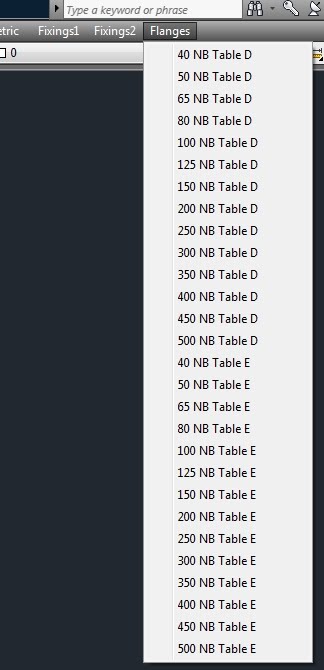
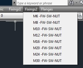
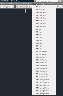
The Flanges just come in as a block. The Fixings1 items come in as individual bits. Fixings2 - they come in as "combos" ie a set of head, flat washer, spring washer, and nut.
To make one of these for yourself is not that hard.
Just fire up Notepad (Look under Start/Programs/Accessories)
and type in something like this:

***MENUGROUP=BILRO1

***POP13
[Fixings1]

[M6 Bolt Head] -insert;"C:/cad/library/3D/fixings/bolter/m6headb";\1;1;0;

Then save it as not a text file, but with a ".mnu" on the end so the file name ends up something like Bilro1.mnu.
The syntax looks a bit arcane, but just go with the flow.... You can see where the path is, and the block name (ie just another dwg file) is, and all the ;\1;1;0; is a shorthand way of saying:
enter,pause,use a scale factor of 1 for X,enter, scale factor of 1 for Y,enter,use a rotation of zero,enter.
To sum up:
; means enter
\means pause for user input
Then you have the fun of getting it into Autocad, so just:
1. Right click on any toolbar, and choose customise.
2. See the little round button with the arrow down the bottom? Hit it.
(There is someone in Autodesk that loves to hide things....)
3. Now pick the Transfer tab up the top.
4. Hit the 2nd button from the right, one that should give a tooltip of "open customisation file".
5.When the dialog comes up look down the bottom-it will say something like "...cuix" or "cui", so change this to legacy files-mnu, and hunt for your file.
Although Autocad does not tell you this, I believe (I can always be wrong!) that it converts it to a cui or cuix file as you open it.
6. On the right panel, expand the + next to "Menus". You should see your new headings there.
7. On the left panel, do the same. You should see the standard menu headings there.
8. Go back to the right panel, pick your first item, hold down shift to select all your items, then drag and drop to the left panel in the position you would like them to occupy.
9. Hit OK.
After some humming and whirring, you should have your menu additions!
As you can see, the Fixings and Flanges are most likely foreign to you as here in NZ we use British Standard Flanges usually.
Now comes the part I had a lot of hassle with: What happens if you get the path name wrong, and need to update it? You would think it should be straight forward, but I did not find it that logical.
How to do it:
Do the same actions as above, but stop at item 7. On the left panel, right click on the items you have added previously and choose "delete". Yes, you are sure! Then from the right panel drag your headings back onto the left panel as before.
I am going to add a few more bits and pieces, and then I hope to post the whole lot as a bundle on http://bilrocad.com/